U020 Going YAKINDU 2 - How to launch, trace and visualize state machines
The first tutorial of the series covered the design of state diagram models and their simulation with reference patterns.
After design, the YAKINDU state chart models are transformed into executable code of different languages and environments. To enable model-level debugging of the state machine implementations, the code can be instrumented to generate so called YET (YAKINDU Execution Trace) traces.
With impulse signal ports, several trace and log sources can be connected. This could be multiple YET traces via TCP, UDP or serial line from state machine implementations together with log and trace data from other components.
Multiple signal ports of different types can be combined into one, synchronizing the received signals. By using scripts, connected devices or applications can be stimulated and their events processed.
This tutorial uses a YET trace over TCP of a simple statechart example (TicToc) and is intended to provide insights into how to attach to trace sources and how to visuale the received data.
Use the tutorial example (Preference Wallet file) to run the example, and watch the screen cast (links below).

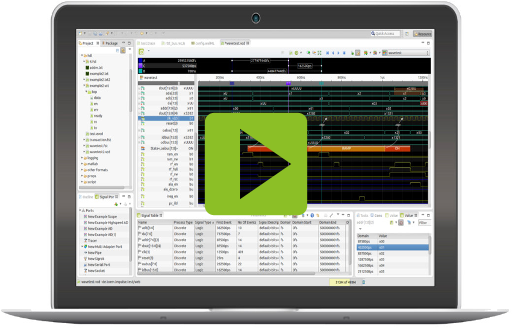
The TicToc trace
To the right , you find the TicToc state chart.
The state machine is has two states Idle and Playing. The single input event toggle switches between these two events. Within Playing state the state machine automatically switches between the states Tic and Toc and raises out events tic and toc respectivley when entering these states. The time interval between state changes is defined by the variable delay.
Below, you find an example YET trace. The format is simply structured. It is text based and consists of a sequence of entries. These can be of three kinds: declarations, initializations, and execution events. Here is an example of a trace:
%version=1 %domain=time_ms %tictoc@Enter,1 #0,This email address is being protected from spambots. You need JavaScript enabled to view it. #0,tictoc.b,t #0,tictoc.i,42.000000 #0,tictoc@StateEntered,main.Idle #2961,tictoc.toggle #2962,tictoc@RunCycleStart #2962,This email address is being protected from spambots. You need JavaScript enabled to view it. #2962,tictoc@StateExited,main.Idle #2962,This email address is being protected from spambots. You need JavaScript enabled to view it. #2962,tictoc@StateEntered,main.Playing #2962,This email address is being protected from spambots. You need JavaScript enabled to view it. #2962,tictoc@StateEntered,main.Playing.active.Tic #2962,tictoc@RunCycleEnd #4961,This email address is being protected from spambots. You need JavaScript enabled to view it. #4961,tictoc@RunCycleStart #4961,This email address is being protected from spambots. You need JavaScript enabled to view it. #4961,tictoc.count,1
To open a file with YET trace content, just double click it to open the impulse viewer (the file ending "*.yet" is assumed by default).
To read the trace from TCP or UDP, you need to add a signal port.

A Signals Port can be opened by the impulse Viewer like a normal file. Instead of extracting the signal data from the file, it is read from an external source (e.g. TCP, a debug adapter or a bus interface).
- To add a port you need to have the Signals Ports view visible (Window > Show View > impulse > Signal Ports).;
- Click the "Add new Port" toolbar button of the "Signal Ports" view and select the port type. ;
- Configure the port settings and press ok.
Ports can be managed most easily with the "Signal Ports" view: (Window > Show View > impulse > Signal Ports). Alternatively you can also use the preferences (Preferences ->impulse > Ports).
- Press the "Edit Port" button of the "Signal Ports" view or use the context menu of the port/adapter element.
- If you have already opened the port in a viewer, press the "Edit Port" button in the viewers toolbar.
The port may read the signal data in one go or spread over a period of time (on-line). impulse allows the analysis of signal data while new data is still arriving.
- To open a port you need to have the Signals Ports view visible (Window > Show View > impulse > Signal Ports).
- Opening a port means opening the viewer with the signal content of the port. Press the "Open Port" button of the "Signal Ports" view or double-click the port item.
- To start the port, press the "Run/Stop" in the tool-bar.
Screen Cast: How to trace and visualize state machines
TCP Port
Modes
After creating a new TCP port, a dialogue pops up:
- In "Normal Client" mode, the adapter tries to connect to the given server and returns with an error if not possible.
- If "Waiting Client" mode is chosen, the adapter tries continuously to connect to the server without error exit.
- If "Server" mode is chosen, the adapter creates a TCP server and waits for exactly one client to connect.
Source Configuration
- Server: Server address or "localhost" (client modes only).
- Socket: Socket number
- Write input to file: Select a file to log the input stream.
You may specify a file "Write input to file" to store the raw input for debugging purpose.
Serializer Configuration
Select the YET reader. No configuration is required.
To open impulse, just double-click on the port. You will see impulse with a slightly different look.

Using Ports
After opening the viewer, the user will find some additional icons in the toolbar of the viewer. They are used to control the data stream from the port and update from within the viewer.
| Icon | Function | Description |
| Edit Port | Opens the port editor | |
| Connect | Enables the user to connect to a port without starting aquisition. Depending on the port design, the port may:
|
|
| Run/Stop | Connects to the port and starts acquisition. To end streaming press again. | |
| Single / Multiple | For scope like ports, this button selects if the acquisition process is:
|
|
| Enable/Disable Updating | If the port generates a floating diagram, this button allows the user to start/stop updating the diagram. To stop the diagram you may also click into the plot area. |
Create a State Chart plot
The plot dialog is roughly divided as follows;
On the left side is defined what to display, on the right side how to display it.
In this case, we want to visualize the state chart model driven by the current state machine. The state chart plot allows the display the current states (on- or offline data) at the current cursor position. Choose the type "Chart" and select the TicToc state chart chart in the field "Chart Style".
Next, we have to define what is to be displayed, i.e. a signal has to be selected.
Click the button right to the priamry source field, and select the "@States" signal.

Launcher Integration
An eclipse launch configuration is a description of how to launch a program. The program itself may be a Java program, another Eclipse instance in the form of a runtime workbench, a C program, or something else. The impulse launch integration enables users to bind an impulse port to a launch configuration.
The port will be opened in an impulse viewer (if its not already open) when the launch is started. Depending on the mode settings, this might be in debug or run-mode only, or always.
Start the launcher
Now we have everything together. As soon as the launcher is started, the application starts running and establishes the TCP server.
impulse is started with a small delay of 600ms - then the server should be active (alternatively you can configure the TCP port to wait).
